Correspondence Groups
The Correspondence Groups dialog lets you author vertex-pair constraints for contact regions: eyelid seals, lip closures, or anywhere two surfaces need to close correctly on a different mesh.
Open it from the Utils menu in the main window.
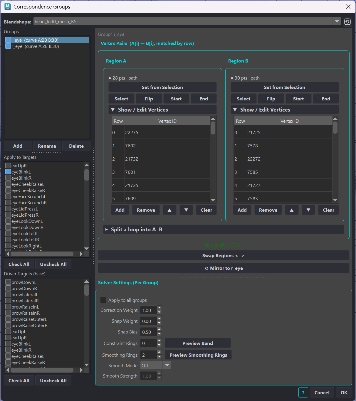
When blendShapes are transferred to a mesh with different rest-state geometry, interpolation does not know which vertices are meant to touch. Correspondence constraints identify those contacts and reproduce the same closure ratio scaled to the target mesh’s local geometry.
Constraints are saved directly on the blendShape node as an attribute and applied automatically during import or transfer when Apply Constraints is enabled.
Layout
The dialog is split into two panels. The left panel manages groups and target filtering; the right panel configures the selected group’s vertex pairs and solver settings. Within the right panel, a resizable divider separates the vertex-pairs area from Solver Settings, so you can drag it to give the vertex table or the solver controls more room.
Left Panel: Groups
Element |
Description |
|---|---|
Blendshape |
The blendShape node whose constraints you are editing. Click the refresh icon to rescan the scene. |
Groups list |
Each group defines one constraint region (e.g. “eyelidL”, “lipsUpper”). The checkbox enables or disables the group without deleting it. The pair count is shown in parentheses. |
Add / Rename / Delete |
Manage groups. Names must be unique. |
Left Panel: Apply to Targets
Element |
Description |
|---|---|
Target list |
Check each expression target this group should apply to. A group with no targets checked is skipped by the solver entirely. Use this to limit a lip-seal group to close expressions only, leaving smile or sneer targets unaffected. |
Check All / Uncheck All |
Quickly toggle all targets. |
Left Panel: Driver Targets (base)
Element |
Description |
|---|---|
Driver list |
Targets applied at full weight as the base under this group’s corrected targets. When a corrective fires on top of a driver (e.g. a jaw-open corrective on top of jawOpen), tagging the driver here lets the solver measure the combined shape instead of the corrective in isolation. |
Check All / Uncheck All |
Quickly toggle all driver targets. |
Right Panel: Vertex Pairs
Pairs are matched row-by-row: Region A row 0 to Region B row 0, row 1 to row 1, and so on. Equal region counts form discrete pairs; unequal counts switch the group to curve mode (arc-length pairing).
Each region panel (A and B) contains:
Element |
Description |
|---|---|
Summary |
Shows the current count, kind (loop, path, or sequence), and direction of the region. |
Set from Selection |
Select an edge loop, edge path, or vertices, then click. A clean loop or path is auto-ordered; a free vertex selection keeps your pick order. |
Select |
Selects this region’s vertices in the viewport. |
Flip |
Reverses the region’s order to fix a crossed pairing. |
Start |
Sets the start vertex (row 0). For a loop, rotates the order to the picked vertex. For an open path, orients it so the picked end vertex lands first. |
End |
Sets the end vertex (last row). For an open path, orients it so the picked end vertex lands last. |
show / edit vertices (collapsible) |
Expands a two-column table of the region’s vertices: Row (its position in the pairing order) and Vertex ID. Clicking a row selects the paired A/B vertices in the viewport. Add appends selected vertices. Remove deletes highlighted rows. Move Up / Down reorders rows. Clear empties the list. Double-click a Vertex ID cell to edit it directly. |
Below the two region panels:
Element |
Description |
|---|---|
Split a loop into A and B (collapsible) |
Load Loop: loads a full closed edge loop into a buffer. Split at 2 verts: select exactly 2 boundary vertices at the desired split points, then click to divide the loaded loop into Region A and Region B, excluding the boundary vertices. |
Swap Regions |
Swaps the contents of Region A and Region B. |
Mirror Group |
Creates the symmetric group on the other side using topological symmetry. The button label shows the suggested mirror name. Requires symmetry to be active on the mesh, and at least one reference target checked. |
Right Panel: Solver Settings
Element |
Description |
|---|---|
Apply to all groups |
When checked, changes to the settings below are applied to every group at once. Target assignments (Apply to Targets, Driver Targets) remain per group. |
Correction Weight |
Master blend for this group. |
Snap Weight |
|
Snap Bias |
Controls which vertex absorbs the correction when Snap Weight is above zero. |
Constraint Rings |
Edge rings around each pair vertex that receive the full correction before feathering begins. |
Preview Band |
Selects all vertices in the Constraint Rings zone so you can see which area receives full correction. |
Smoothing Rings |
Edge rings beyond the constraint band that participate in feathering. |
Preview Smoothing Rings |
Selects all vertices in the feathering zone. |
Smooth Mode |
Post-feather smoothing applied to ring-neighbourhood vertices. Off: no smoothing. Smooth (Laplacian): single averaging pass. Relax (Taubin): two-pass smooth that resists delta shrinkage. |
Smooth Strength |
Strength of the ring smoothing pass. |
What Problem It Solves
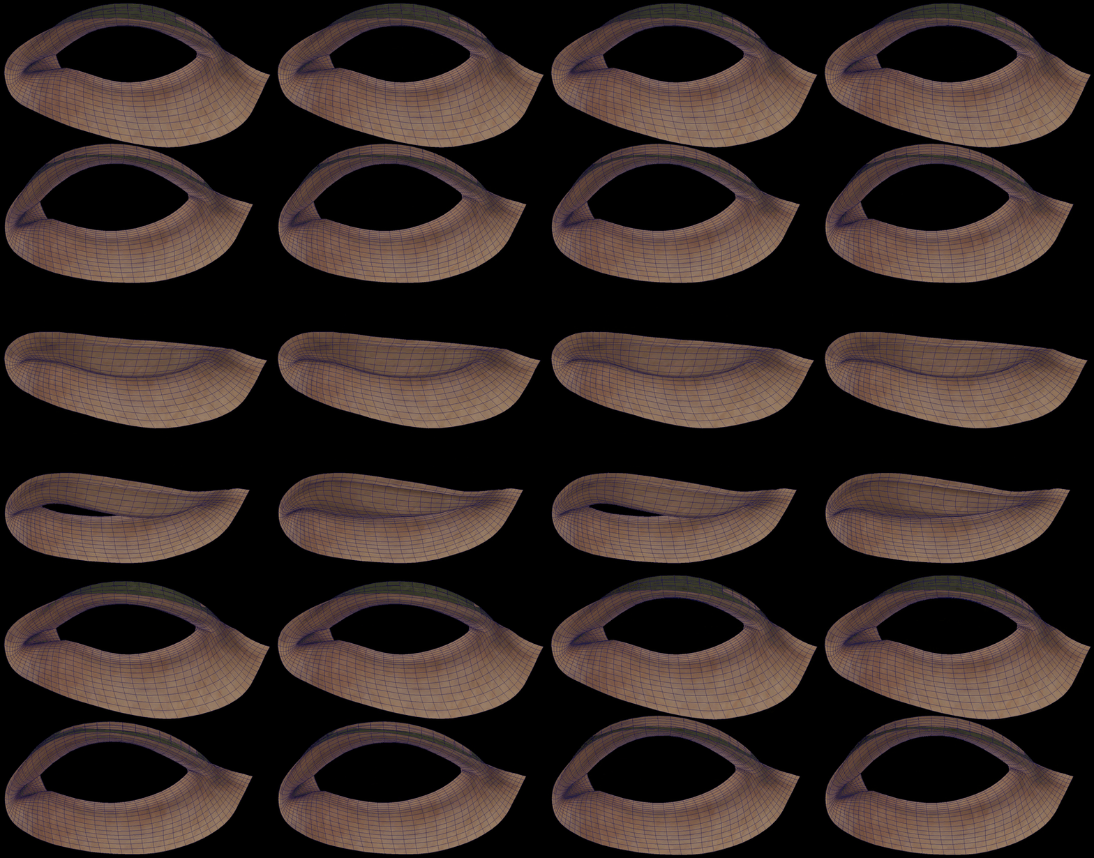
An eyelid that closes 70% on the source mesh might close the wrong amount on a target mesh whose eyelid gap is wider or narrower at rest. The result looks either too open or already sealed before the expression reaches full strength.
The correction is applied after interpolation as a post-process, and it blends smoothly into the surrounding mesh so there’s no hard seam at the correction boundary.
The Core Idea: Signed Ratio Preservation
For each pair of vertices (A and B), the solver measures the “closure ratio” in the source expression.
Rest gap. At rest, A and B are some distance apart. The solver records both the distance and the direction between them as the reference axis.
Source ratio. In the expression, the solver measures how much the gap has changed along that axis as a fraction of the rest distance. A ratio of 1.0 means fully open (at rest distance). A ratio of 0.0 means fully closed. A negative ratio means the vertices have crossed through each other, which happens during a full seal.
Target correction. The solver multiplies that ratio by the target’s own rest-gap distance to get the desired gap in the target expression, compares it to what interpolation produced, and nudges A and B to close the difference.
The reason the solver uses a signed projection rather than plain Euclidean distance is that an over-closed pair, where vertices have crossed through each other, has a positive absolute distance that is indistinguishable from an open pair if you only measure magnitude. The signed projection treats the rest direction as an axis (positive = open, zero = touching, negative = overlapping), so vertices that authentically cross on the source correctly drive the target pair into overlap too.
Snap Weight and Snap Bias
By default the solver uses ratio preservation, correct for partial expressions. Two additional controls override that for full-contact situations, such as snapping one region to another after an Index transfer. Neighboring vertex smoothing is controlled by the Smoothing Rings setting.
Snap Weight blends from ratio-based correction toward full 3D contact snap.
At
0.0(default) the solver preserves the closure ratio scaled to the target’s rest gap. Partial expressions interpolate correctly.At
1.0the solver drives pair vertices to full 3D contact regardless of ratio. Use this when vertices must always meet exactly.Values in between blend continuously between the two behaviours.
Snap Bias controls which vertex absorbs the correction when Snap Weight is above zero. Think of it like normalized weights in a pointConstraint.
0.5splits the correction evenly. A and B both move toward each other and meet in the middle.1.0moves B all the way to A’s position (A is the anchor). A stays put.0.0moves A all the way to B’s position (B is the anchor). B stays put.
Snap Weight determines how much of the correction is contact-based. Snap Bias determines which vertex moves to achieve that contact.
Feathering: Ring-Distance Smoothstep
Correcting only the pair vertices would create a sharp crease at the edge of the correction. The solver spreads the correction outward using a ring-distance feathering pass.
Starting from the pair vertices, the solver walks outward along mesh edges and assigns each vertex a ring number: 1 for immediate neighbours, 2 for the next ring out, up to the configured maximum. It then blends the correction in a single inside-out pass:
Ring 0 (pair vertices) are pinned to their corrected positions.
Ring 1 blends strongly toward the average of its ring-0 neighbours.
Each successive ring blends progressively less, following a smoothstep falloff.
Because each ring blends against already-feathered neighbours, the correction propagates outward in one pass. No iterations, no strength parameter.
Per-Group Target Filtering
Constraints are authored as named groups. Each group optionally lists the target expressions it applies to. The solver activates a group only when processing a matching target. A blink group fires on a blink target and ignores the other targets.
Groups with no pairs or no matching targets are skipped with no overhead.